
Bioprocess Facility Design — Layout Rules And Configurations
 The impact of COVID-19 vaccines and rapid expansion of new therapies facilitated by cell and gene technology has changed some of the landscape for facility design over the past few years. Construction of new facilities and massive renovations to existing facilities have provided a unique opportunity to rethink basic design strategies and use new technologies to build a better facility much faster than before. We have also seen the unprecedented drive to single-use systems (SUS) for expediency and compliance, while operations faced a shortage of those same materials.
As we discussed in our previous article, there are multiple variables that must be considered in the layout of a biopharmaceutical facility, and many of these variables are interdependent. The adoption of single-use systems (SUS) is allowing for a shift in the balance of those variables to enable smaller and more modular facilities. This article will explore modern facility design options and configurations, and the realities of building a facility around the SUS process technology. We must also consider the growing needs of the growing BL-2 processes, viral vector processes, and the need for containment.
Basic Principles Of Facility Layout
Once we understand our basic constraints and have outlined our processes and risks completely, we can start positioning the equipment and the processes in the facility. The following are some basic layout techniques that will provide the adjacencies from the process core, or building blocks, of how a facility should look.
The actual process area should be limited to the space the operators need to interact with the equipment, and that should be kept to an absolute minimum. This means only the manipulated ports, aseptic connection points, isolar interfaces, BSCs, and utility drops. This classified Grade C or Grade D space should house sample ports also. This will be Grade C space if we are in upstream or downstream processes where any part of the process or cell culture/biological material is manually exposed. It can be Grade D if it is a buffer or media prep.
All large, fixed, stainless steel equipment needs to be in non-classified “gray” space. The gray space can include any and all fixed piping systems, valving, instrumentation, conduits, and manifolds. This is a key economic trade-off of space — unclassified grey space (@ $150-200/sq. ft.) versus Grade C space (@ $600-700/sq. ft.).
Large upstream skids like bioreactors need to be in classified space due to the many connections, sample ports, and setup activities. Likewise, downstream skids like chromatography and tangential flow filtration (TFF) have many manipulation points and cartridge changeover points that require cleanroom space to prevent bioburden and cross contamination.
Using a biosafety cabinet (BSC) for open manipulations (e.g., opening seed vial) with a Grade C background is generally accepted practice for traditional biopharmaceuticals since the downstream processes will have orthogonal viral reduction methods and sterilizing filtration. For cell and gene therapies, a more critical eye must be placed on determining the appropriateness of the background classification, determining segregation of operations, and determining if a BSC provides sufficient protection.
Functionally closed processes for traditional bioprocesses can be in an ISO 8 in operation (in the U.S.) or Grade D (in the EU) environment. However, due to biosafety concerns, cross contamination, and technical challenges of achieving functional closure with living cells, cell and gene therapies require a detailed review by process on applicability of functional closure.
With SUS methods, the need for co-located wash rooms with floor drains and high moisture levels should be eliminated. Using process-integrated sterilizers is also unnecessary, since the process flow paths (vessels, tubing, and instruments) are the SUS. The only sterilizers that may be needed are the exit/decontamination sterilizers that will process biosafety level (BSL) 1-3 material or live cell culture prior to disposal.
For BSL-1, viral vectors, and BSL-2 (including unscreened donor material), there needs to be a clear uni-directional strategy of clean material in, infectious material out, product (viral cleared or not) and waste out. This is critical to prevent cross contamination and to comply with Annex 1, Annex 14, and CDC guidelines.
Along with the material flow paths, the personnel path must be uni-directional in order to operate within the environment and not have the operators become a source of bioburden in, cross contamination within the process suites, or a segregation or decontamination method for personnel exit.
Based upon the risk profile of the product, several process steps can be co-located in the same suite if a material flow and personnel flow method has been developed.
Generally, processes that use viral inoculation must separate a pre-viral (upstream) processing suite from the post-viral (downstream) processing suite as required. This separation is similar and required for all BSL levels. Processes at different BSL levels must be separated from one another (e.g., BSL-1 from BSL-2), even for the same product in a single-product facility.
SUS technology can eliminate the need for tanks for media and buffer prep, as well as the need for washing and cleaning of those vessels. The key is a controlled Grade C or Grade D area to execute the dispensing and addition. Alternatively, one could buy premade media or buffer to assure an easy transfer and use a Grade D suite. Either way, the material needs to enter the processing area compliantly, not dragged in from a warehouse dispensary. As shortages continue in the industry, supply chain risk may become a driving factor in the consideration of stainless steel vs. single use in media and buffer preparation.
Weighing and dispensing is often a logistical problem that could contaminate the processing suite due to the movement of material and the activity it requires. A workable option is to incorporate a flexible, portable “pop-up” plastic isolator (with negative HEPA pressure) to execute material dispensing (of media, buffer, or even a potent compound. This last option also reduces footprint, because it can allow a normal processing suite to function as a dispensary and eliminate another room/suite.
The one challenge with the medias being used today is that many are provided to the user as non-sterile. The transfer of any non-sterile (meaning it contains bacteria and fungus) needs to be done within a SUS closed transfer. In addition, there needs to be a containment around the media in case of a spill due to a connection failure. The most significant risk is working with a media powder. Even with a closed transfer bag system, the disconnect is never perfectly clean and there is always a tear/perforation risk.
SUS technology precludes the need to move equipment around and replaces nearly all vessels under 1000 liters. Combined with the use of pre-sterilized hoses, ports, and aseptic connectors, SUS can also allow targeted rooms to become multi-process, multifunctional, and multiproduct. This can further reduce the facility footprint, the number of rooms and airlocks, and internal traffic. If managed carefully and sanitized, this is ideal for CDMOs. SUS for hold bags are typically easier to source and have multiple suppliers while SUS for mixers typically have a proprietary design that limits sourcing.
Layouts need to account for the support, storage, logistics, and orderly arrangement of single-use tubing sets and the skid and room ancillaries. Special attention needs to be made to the density of the SUS (plastic) as they can become an issue for fire protection. Seek guidance on fire suppression for high-density plastic component storage.
Implementing these considerations could result in having several parallel non-dedicated suites that can function as “flex-processing space.” These would be sized to accommodate the variety of processes, in order to maximize use and minimize idle time. These rooms must have the full complement of utilities for use and should include HEPA in/out (using bag-in/bag–out, and/or room vaporized hydrogen peroxide [VHP]) to allow them to accommodate wide product use, BSL-1 through BSL-3, potent compounds, and viral-based production.
In summary, we focus on the workflow of the operator, using SUS to consolidate the number of steps, eliminate fixed vessels, use (cheaper) grey space for large or fixed tankage, incorporate flexible/disposable isolators, and keep media isolated/separated from the open processes. Now we have a concept to begin the layout.
Layout Rules And Options
In order to layout the facility, the EU and the FDA have provided enough guidance and recommendations to provide a starting framework.
- The flow of people, equipment, raw material, products, and waste in a uni-directional manner has been a good practice for traditional bioprocess, but is expected by the regulators for viral vector and BSL-2 facilities. Procedures can only be part of preventing crossover flows, and the layout should force all personnel and components to enter clean, participate in the process, and exit. The facility layout should prevent travel against this direction, including movement between various suites. This is the first very clear safeguard against material/product cross-contamination between suites, as well as bioburden. If contamination arises, it will not be spread to other suites via personnel or other means — it will stay contained in that suite system (a critical factor for facilities processing multiple viral vectors). This concept necessitates that processing suites exist in parallel and that all aspects flow into the processing suite and out an exit path. The result is a process flow that prevents crossover and cross-contamination.
- The entrance to any suite is always a clean corridor and increasing levels of EU–grade spaces, from CNC to D to C. Each change of grade contains an airlock to separate the grades (and suites) and provides a physical buffer so one grade minimizes the potential to contaminate the next.
- The exits from all processing suites must provide a declining series of room/suite/airlock grades (C to D to CNC), with airlocks or air-sinks ultimately exiting into a “dirty corridor.”
- Gowning is a clean activity and is always attached to a "clean" or supply corridor, while de-gowning is a "dirty" activity and is attached to the "return" corridor that handles waste. The gowning and de-gowning rooms must always be separate.
- Because of the differing methods of decontamination/cleaning for people versus materials, people never share the airlock with a piece of equipment or material. That is specific in Annex 1.
- Any utility function, such as equipment preparation or storage, must be designated as a clean or dirty function and service the suites from one side, not both. As an example, if a skid or equipment is moved out of a suite for maintenance, it is a dirty function that enters a dirty corridor and travels into a service suite. The function of that service suite should be to clean, sanitize or sterilize, dry, and store that equipment. The exist of that cleaning process suite should be a cleaning/decontamination function that is accessible (after a series of airlocks) to the clean corridor, so the unit can be reused. Using SUS and operating without any mishaps or contaminations should minimize or limit these service areas, because most skids can be cleaned inside the process suite. Facility designs that use through wall ports for buffer media transfer help mitigate constant movement of equipment in/out of suites, reducing cross contamination risk. However, this design increases the complexity of operational setup.
- Ultimately, this concept forces a circular pattern of working from clean to dirty, dirty to retool/re-gowning, and a return to clean.
3 Basic Layout Models
Based on the constraints and regulatory rules discussed above, there are three basic layout models.
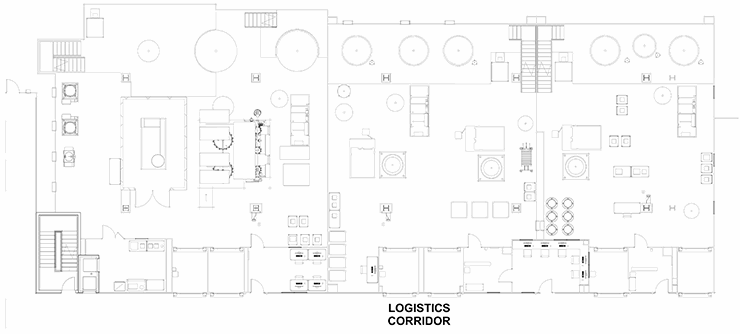
Train
A “train” of linear clusters of suites with a common corridor, each of which is geared for a specific process operation. This allows processing to start in the lead/upstream suite (e.g., bioreactor) and progress down the train (e.g., chromatography operations). When one product is in the downstream suite (e.g., chromatography), a new bioreactor can be running the upstream process of the product again in a campaign. This model is well-suited for several types of commercial applications, especially single-product facilities that deal with a non-potent compound. The train has logistics corridors on to act as a supply route and for personnel movement. The supply corridor does have a significant number of material air locks (MALs) and personnel air locks (PALs) that isolate the process and infectious materials inside. This example is most suitable for larger-scale traditional biotechnology manufacturing such as cell culture vaccines or monoclonal antibodies. In this application, the raw materials/buffers/media are pumped in from adjacent suites and the product is pumped out. The logistics corridor must accommodate waste and personnel by a coordinated control of the MALs. This is clearly not ideal, but workable.
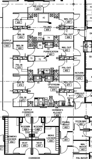
Stack
A “stack” of several larger, parallel multiple-purpose suites with a clean supply corridor on one side and a dirty return corridor on the opposite side. This configuration isolates each suite via airlock systems, so any one major process is performed independently and is contained. If the MALs and PALs are an air "bubble," three independent operations (upstream, downstream, and filling) could be done simultaneously. This configuration is the most ideal configuration from a compliance viewpoint. The product of any suite can be pumped or transferred via SUS to be performed in the next suite. This layout works best for commercial multi-product bio-production or for a contract manufacturer (CMO). Suites could accommodate pre-viral or post-viral production.
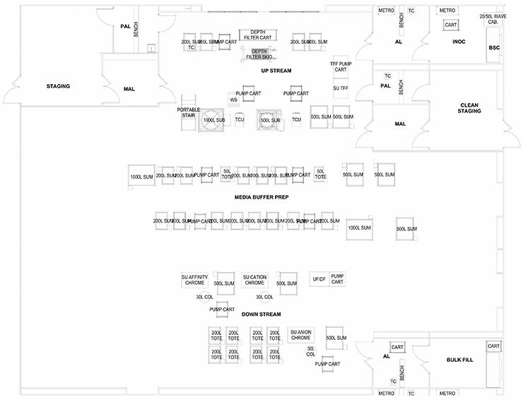
Ballroom
The last configuration involves a series of preparation suites leading to one large multipurpose “ballroom” that services several process and products. This is ideal for efficiency in the use of technicians and scientists as they can monitor several operations. The ballroom will have several exit paths depending on the product bulk handling and packaging. This configuration is ideal for R&D and clinical production. The weakness of this approach is the lack of product and process segregation, which presents cross contamination as a major risk.
The ballroom design does have an application in personalized medicine, cell therapy, and some gene therapy production. If the operational center of a ballroom was strictly a media/buffer/supply material staging area and the production processes, manipulations, and operations were in isolators or other truly closed systems, then we could envision scaled-out production capability of small batches.
These configurations offer some generic layouts based on the regulations and constraints discussed above. The process engineer must work with a layout specialist or architect to decide which processes must be adjacent, separated, isolated, or combined. With the core defined, the balance of the facility can be detailed with support corridors, locker rooms, utility systems, and warehousing.
Editor's Note: This article has been updated since its original 2016 publication to reflect industry changes over the past five years.
About The Authors:
 Herman Bozenhardt has 45 years of experience in pharmaceutical, biotechnology, and medical device manufacturing, engineering, and compliance. He is a recognized expert in the area of aseptic filling facilities and systems and has extensive experience in the manufacture of therapeutic biologicals and vaccines. He has a B.S. in chemical engineering and an M.S. in system engineering, both from the Polytechnic Institute of Brooklyn. He can be reached via email at hermanbozenhardt@gmail.com and on LinkedIn.
 Erich Bozenhardt is the lead process engineer for regenerative medicine operations. He has 15 years of experience in the biotechnology and aseptic processing business and has led several biological manufacturing projects, including cell therapies, mammalian cell culture, and novel delivery systems. He has a B.S. in chemical engineering and an MBA, both from the University of Delaware.