
Developing & Implementing A Continuous Bioprocess Control Strategy
By BioPhorum

At its heart, continuous processing potentially simplifies manufacturing by operating at a steady state. Continuous processes have already been developed for several small molecule therapeutics, but the complexities of biologics have slowed the adoption of continuous bioprocessing. A key challenge is the necessity to link unit operations to operate a continuous bioprocess.
This article defines a standard template approach for developing and implementing a continuous bioprocessing control strategy. It provides a visual and technical aid for linking common unit operations in the continuous biomanufacturing process and highlights considerations when selecting control schemes. This article outlines a means of assessing the unique design needs of a continuous bioprocess to establish a connected product flow across all integrated unit operations. This approach includes three steps:
- Define process: determine the order of unit operations and identify process linkages.
- Identify input and output mode pairing: define the material flow in and out of each unit operation pairing as varying, constant concentration and/or volumetric flow.
- Assign conserved control scheme: select from three conserved control schemes for connectivity of unit operations.
Process Flow Considerations
The unit operations and regulatory batch definitions required to produce a monoclonal antibody (mAb) have been well defined. Each of the unit operation functions is maintained in the transition from batch to continuous. There is often a range of solutions at each step to achieve process intensification at the unit operation level and for the overall process. However, the way a batch is defined in the process (e.g., time, volume, or product mass) may influence the control strategy.
To create a control strategy, assumptions were made based on the process flow steps in Figure 1. They include:
- the perfusion bioreactor is taken to include both the cell retention device and reactor vessel as a single entity generating a constant volumetric flow,
- the Protein A (ProA) capture step is via continuous multi-column chromatography (CMCC) that enables continuous loading but has sequential intermittent elution, and
- the low-pH viral inactivation (LpH VI) step is usually one of two formats: plug flow reactor, where material continuously moves through a flow path with a specified residence time, or dual tank, where material is collected and held for the requisite time in sub-batches before forward processing.
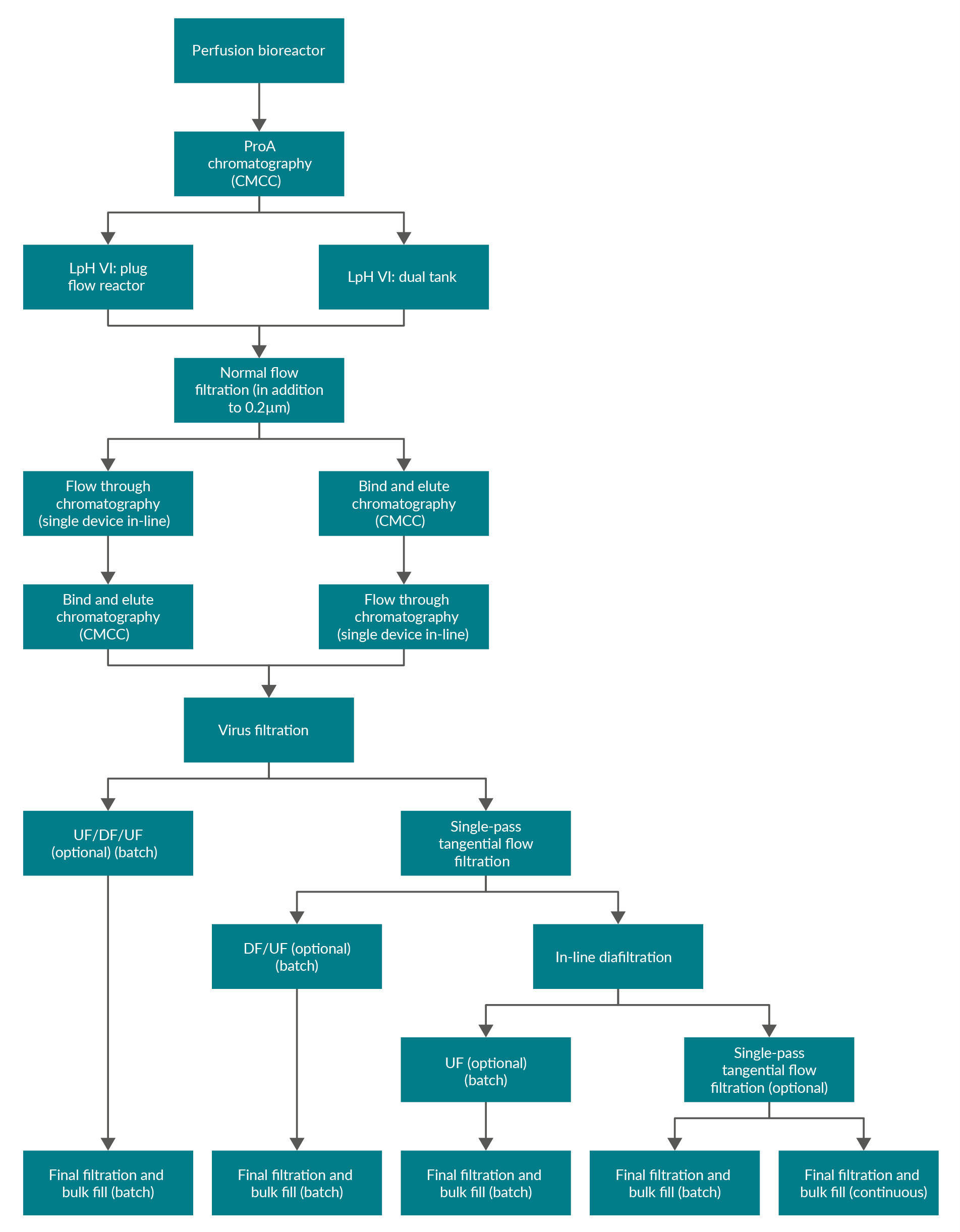
Figure 1: Block flow diagram of example process layouts. ProA – Protein A, CMCC – continuous multi-column chromatography, LpH VI – low-pH viral inactivation, UF – ultrafiltration, DF – diafiltration.
There are multiple options for the creation of bulk drug substance. Figure 1 shows, for a process with nine to 11 unit operations, that there are eight to 10 interfaces where product exits one unit operation and enters another. However, considering the diversity of processes, there are many more potential linkages (Figure 1 shows 22 different linkages). Understanding product handoff from one unit operation to another is key in developing an integrated process and could impact the choice of process intensification solution at the unit operation level.
Figure 2 shows how each linkage between two individual unit operations can be characterized by the product concentration (c), volumetric flow rate (F), and the resulting product mass flow (m). This is a visual representation used to indicate consistency or change over time and is not a reflection of exact processing conditions in terms of direction, magnitude, or rate for each parameter, or relative to other parameters.
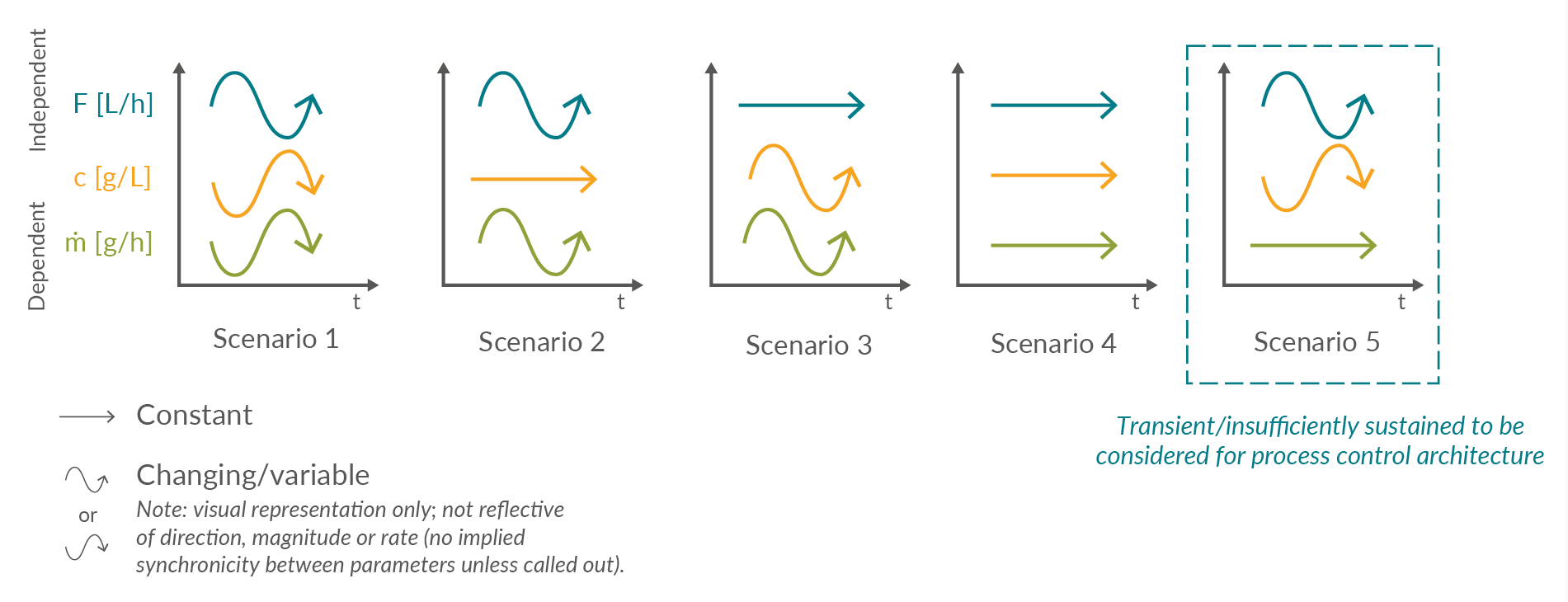
Figure 2: Qualitative visualization of the potential product stream parameters over time (t), characterized by volumetric flow (F), concentration (c), and resulting product mass flow (ṁ). Click on image to enlarge.
Five scenarios are identified:
- When the volumetric flow rate and concentration vary in a non-synchronic manner, the resulting product mass flow rate changes over time. This scenario assumes that flow rate and concentration vary inversely and proportionally in a 1:1 ratio. Other types of non-synchronic variation are possible. Examples: normal operation of a perfusion bioreactor or the Protein A eluate stream.
- Constant concentration and varying volumetric flow rate resulting in a variable product mass flow. Examples: single-pass tangential flow filtration (SPTFF) or filtration of a homogeneous feed with either a fouling filter or variable flow rate to regulate product mass flow.
- When the volumetric flow rate remains constant, and the concentration varies, a varying product mass flow rate will result. Example: a continuous viral inactivation.
- Behavior is probably only achievable for short durations of time, where both constant flow rate and concentration result in a constant product mass flow. Examples: during a flow-through chromatography or non-fouling filter step.
- This is a theoretical stream composition, where volumetric flow and concentration are inversely proportional and synchronized to achieve a constant product mass flow. Scenario 5 is not sufficiently sustained over the duration of the unit operation to be considered a unique condition and is therefore typically considered a subset of Scenario 1.
Unit Operation Interface Considerations
A review of the 22 potential linkages between unit operations (Figure 1) identified five possible input or output scenarios (Figure 2). Scenarios 1 to 4 are considered distinct. Scenario 5 can be considered a subset of Scenario 1 and therefore does not necessitate its own classification of control.
Material is supplied to a biomanufacturing unit operation with either varying volumetric flow (Scenarios 1 and 2) or constant volumetric flow (Scenarios 3 and 4). Both options can be further subdivided depending on whether the concentration is varying (Scenarios 1 and 3) or constant (Scenarios 2 and 4). Similarly, the product mass flow output from a biomanufacturing unit operation can then be categorized as either constant or varying.
Flow control strategies in unit operations can be operated in different modes. The simplest option uses the output flow rate from the preceding unit operation to determine the input flow rate of the next. The most sophisticated option is the steady-state flow, where the fill level of the intermediate tanks is kept close to a predefined setpoint with a proportional integral derivative controller, allowing for small adaptions in flow rate. Here, only minor differences in the flow rate will occur. The third option is to control the flow rates according to certain predefined thresholds in fill level or recipe stages with a state-based controller, where the flow is adjusted to predefined values. The fourth option is the on/off control, where the flow rate is either running at a high value or zero. The transition from one output scenario to an input scenario between the unit operations forms the basis of the underlying building blocks of the liquid and product mass flows through a continuous process. Figure 3 illustrates 16 unit operation interface permutations arising from the four input and output scenarios.
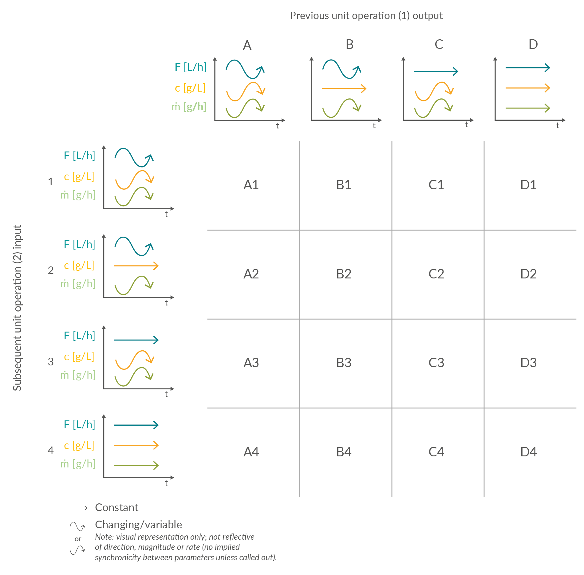
Figure 3: Matrix of potential product stream interfaces between unit operations in an integrated continuous process based on example scenarios of product stream volumetric flow (F, L/h), concentration (c, g/L), and resulting mass flow (m, g/h). Click on image to enlarge.

Intermediate Vessel Considerations
There are advantages to including an intermediate vessel between unit operations in a continuous process. These include normalization of flow, pressure equilibration, and minimization of perturbation propagation. The inclusion of an intermediate vessel also enables relative decoupling of unit operations to aid process control, process deviation management, and equipment failure mitigation. If the surge vessels are large in comparison to the flow rate, they can provide time for maintenance and replacement. However, additional vessels also increase the overall system cost and require periodic cleaning and potential sanitization.
Automation complexity is increased through additional control elements, including sensors to maintain a fill level or pressure within specific ranges, hold-up volume, local residence time, and the residence time distribution. Therefore, the size of each intermediate vessel should be considered based on minimizing the impact of the additional volume, while ensuring the vessel operates above a minimum level to prevent air entrapment and ensure sufficient mixing, where applicable, and below a maximum to prevent integrity loss and residence time broadening. In a closed-system operation, dead zones in the process flow should be taken into account when switching between surge tanks for tank cleaning or replacement.
Control Schemes
Integrated continuous bioprocesses vary depending on the molecule, manufacturer, and facility; however, the interfaces between the unit operations are conserved. This article is focused on the input and output scenarios considered, based on industry experience, the most likely options for continuous mAb processing. The 16 possible permutations of four inputs and four outputs can be consolidated into three control schemes (Figures 4, 5, and 6).
Consolidated Control Scheme 1
This outlines a process linkage in which there is no intermediate surge vessel. This is unique to this control scheme. It is anticipated that in-line concentration monitoring through, for example, ultraviolet (UV) and totalizing flow control will be provided to regulate product mass and/or volumetric load across the subsequent unit operation. Alternatives to UV tracking may be employed depending on the product, accuracy and resolution of the detection system, and the technology maturity. However, for simplicity, UV tracking is used as a generic descriptor for real-time quantitative detection.
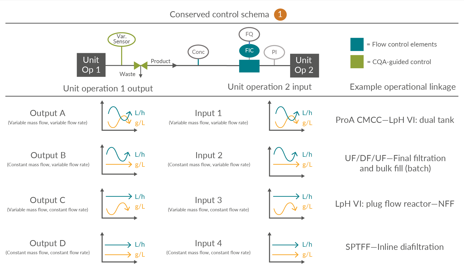
Figure 4: Conserved Control Scheme 1: control approach for unit operations not requiring a surge vessel. FQ flow totalizer, FIC flow meter, PI pressure indicator, UV product concentration measurement and Var. Sensor unit operation-specific process sensors. ProA – Protein A, CMCC – Continuous multi-column chromatography, LpH VI – Low-pH viral inactivation, NFF – Normal flow filtration, UF – Ultrafiltration, DF – Diafiltration, SPTFF – Single‐pass tangential flow filtration, CQA – Critical quality attribute. Click on image to enlarge.
Consolidated Control Scheme 2
This is one in which a small surge or cycle surge tank is required due to a mismatch between the required output and input material cadence and vice versa. This scheme incorporates a UV monitor and totalizing control support to manage mass loading across the subsequent unit operation. Due to the introduction of an intermediate vessel, an additional pump is required to manage the flow rate from the surge vessel into the subsequent unit operation.
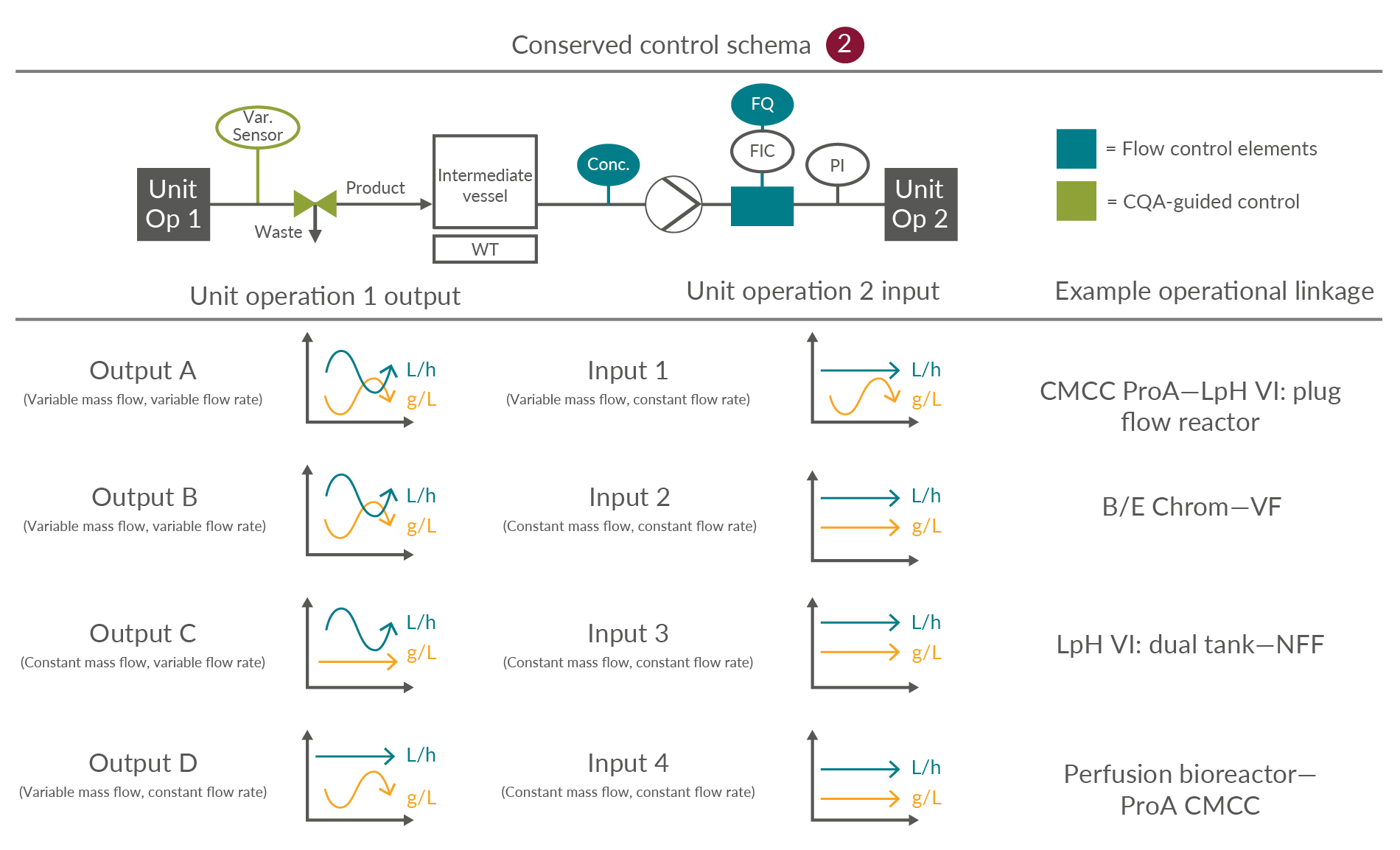
Figure 5: Conserved Control Scheme 2: control approach for unit operations optionally requiring a surge vessel. FQ flow totalizer, FIC flow meter, PI pressure indicator, UV product concentration measurement, and Var. Sensor unit operation-specific process sensors. ProA – Protein A, CMCC – Continuous multi-column chromatography, LpH VI – Low-pH viral inactivation, NFF – Normal flow filtration, UF – Ultrafiltration, DF – Diafiltration, VF – Viral filtration. Click on image to enlarge.
Consolidated Control Scheme 3
This requires an intermediate vessel due to the mismatch between the desired material cadences of output and input unit operations. Unlike in Control Scheme 2, this linkage necessitates a batch pool tank to facilitate the combination and homogenization of output material over a longer time interval up to the inclusion of the entire batch, prior to forward processing, as illustrated by B4 LpH VI: dual tank to normal flow filter.
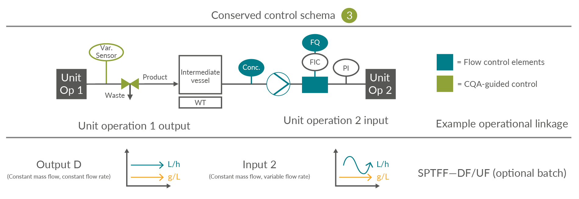
Figure 6: Conserved Control Scheme 3: control approach for unit operations requiring a surge vessel. FQ flow totalizer, FIC flow meter, PI pressure indicator, UV product concentration measurement and Var. Sensor unit operation-specific process sensors. SPTFF – Single-pass tangential flow filtration, UF – Ultrafiltration, DF – Diafiltration, CQA – Critical quality attribute. Click on image to enlarge.
Bioburden Control And Other Risk Considerations
Bioburden control is critical for maintaining low bioburden levels in continuous bioprocessing, with different strategies required for success at each unit operation. Strategies used for maintaining low bioburden levels in batch processes may not be sufficient for longer processing times. Successful control strategies will include process design for the prevention of microbial incursion, maintenance of system integrity, monitoring for detection of bioburden, and predefined escalation and response protocols. Each of these elements must be evaluated using a risk assessment approach.
Conclusion
This article reduces the product handoff between one unit operation and the next to just three possible control schemes, which considerably simplifies the description of connections between process steps. By starting with an example mAb platform process, 22 discrete connections were identified. These were rationalized to 16 possible combinations based on the nature of the volumetric mass flow out of a unit operation and the volumetric mass flow into the subsequent operation. With just three control schemes relevant for the interconnection of process steps, interconnections can become conceptually and physically modular.
This is important as it drives simplicity in building the process. It creates the possibility to have a standard set of valving, surge tanks, and process analytical technology employed for each control scheme. This simplifies the number of skids that must be ordered and may help reduce the inventory required to handle deviations or process failures. Additionally, by using the same interconnection strategy between multiple operations, it simplifies the control strategy: the same control strategy can be cut and pasted between all connections that use the same scheme.
This article summarizes a recent BioPhorum publication on the topic. To read more, check out the full paper in Continuous bioprocessing control and connectivity.