The Influence Of Flows In cGMP Architectural Design
By Geoff Middleton, architect, cGMA, Inc.

cGMPs guide and direct designers and manufacturers to avoid or prevent contamination and mix-up of materials and equipment in manufacturing facilities. There are two fundamental tools in the design and operation of a manufacturing facility that are used to accomplish these goals: facility layout and a matched set of procedures.
During the development of facility layout, strategic decisions balancing the roles of layout and procedure have a critical role in defining the goals that layout must satisfy, as balanced with a matched and tailored set of operating procedures. Once the layout is complete, a set of flow plans, typically part of a regulatory review drawing set, expresses to the knowledgeable reader the roles played by the layout and what remains to procedure to complete.
This discussion will examine how the interplay of layout with procedure may be resolved, how this resolution affects facility layout during design, and how flow plans may indicate to the reader the need and criticality of supporting procedures.
Flows’ Influence On Layout
If we consider many conventional functions for a facility, such as classrooms, apartments, hotel rooms, offices, etc., the notion of flows plays a little role. Access, adjacencies, and efficiency will be the primary drivers of these facility types. Often, a corridor lined with rooms or units on each side offers a straightforward diagrammatic configuration.
To a significant degree, GMP mandates of segregation, contamination control, and mix-up avoidance, as embodied by flows, influence facility layout in directions quite different from the conventional, double loaded corridor diagram described above. A GMP manufacturing layout will express flows and desirable accessibilities and segregations as integral features of the design. The layout expresses flows as actual construction, embodied by walls and doors, manufacturing suites, corridors, and transition spaces. Each room on a layout has specific roles to play in accommodating manufacturing and segregating flows and environments from one another.
Flow Plans
Flow plans are routinely overall floor plans or general arrangements of the facility at each operating level with added path and directional graphics for each of several specific movements into, out of, and though the facility. These are generally separated into two primary categories: people and materials.
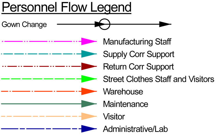
For people flows, the drawing may distinguish between several functional groups. At minimum, the drawing will always include manufacturing staff. Additionally, there may be an assortment of other groups such as visitors, maintenance staff, process support staff, warehouse staff, or other specific subsets of staff appropriate to describing the design and operation of the facility.
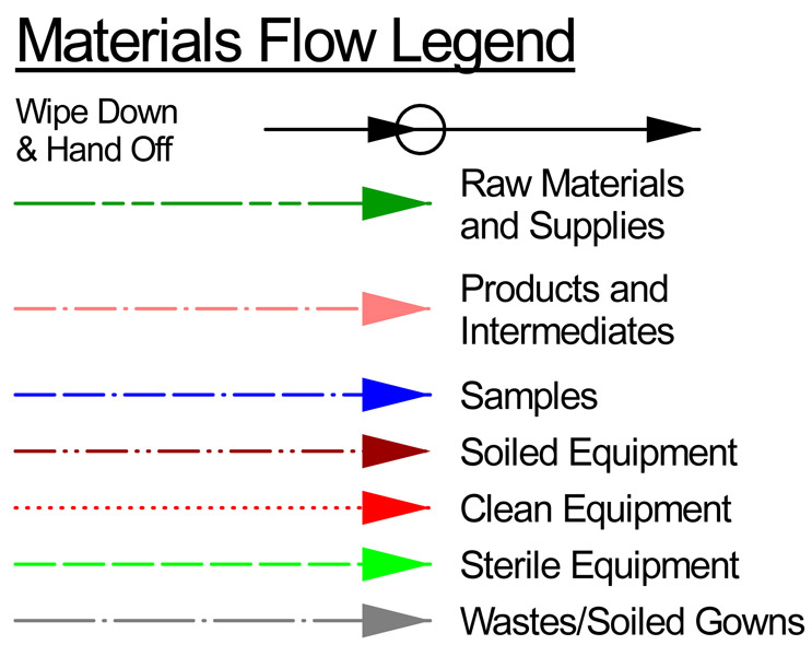
Material flows often include:
- raw materials and supplies
- solid wastes
- soiled, clean, or sterile equipment
- process intermediates
- finished product
- samples, etc.
Similar to personnel flows, incorporating additional categories and details specific to the facility, its operation, the nature of the process, and the design.
The Bases Of Flows
So, why do we care about flows or generate flow plans? And what does one learn about a facility through them? A set of core concepts of good manufacturing practices form these bases. Flows find their origin in GMPs that guide and direct designers and manufacturers to avoid or prevent contamination and mix-up of materials and equipment in manufacturing facilities.
First, some high-level definitions:
Contamination
Contamination is a catchall term that encompasses a wide array of materials from a set of independent sources. All may be defined as unintended materials entering a manufacturing area or process. A summary follows:
- Outside Environment: A wide range of materials and organisms common to the natural, external environment would be considered contaminants within a GMP facility. A complete list is not intended; however, examples include pollens, dusts, molds, insects, vermin, any materials that could serve as nutrition for adventitious organisms, and adventitious organisms themselves, both macro and micro, etc.
- Internal Materials Not Intentional: Any materials intentionally introduced into a GMP manufacturing environment, or produced therein, for a specific purpose that ends up in the wrong place or in the wrong process or stage of a process, can be a contaminant. For example, a raw material intended for a particular solution inadvertently introduced into another process or solution would have become a contaminant. This category can include “Mix-up,” which is discussed in greater detail below.
- Other Products: Any facility that manufactures multiple products, whether concurrently or sequentially, must ensure that they do not influence or contaminate one another.
- Multiple Batches of Same Product: As products produced by GMPs must reliably trace and make record of contributing components and materials in each batch of any product, segregation of batches of any single product becomes critical. In the event of failure of a batch of product in release testing or recall due to events in use that trace back to substandard contributing components or specific materials, strict batch segregation assures that adjacent batches of the same product are unaffected.
- Early To Late Stage Components Or Intermediates Of A Product: As processes progress from early stage to final stages through a set of process steps and equipment, various refinements and clearances are accomplished. Should earlier stages of processing inadvertently be reintroduced at a later process stage, they could comprise a contaminant to the process at the later stage, effectively undermining its intended clearances, purity, and refinements.
Mix-up
As a category, mix-up refers to inadvertent misdirection of similar or similar-looking items to an incorrect use. Mix-up can apply to a temporary state, such as clean or soiled, or a stable state, such as confusing salt with sugar as raw materials, or fresh supplies with used waste. In all cases, a mix-up can undermine the process and lead to loss of batches or risks to patients. A general set of category descriptions of mix-up follows.
- Clean – Soiled or New – Used if SU: In the normal course of processing, pieces of equipment are utilized and product contact surfaces become soiled. These then require cleaning and, in some instances, autoclaving or steaming in order to return them to service for the next use.
In the parallel case of single-use product contact equipment, the membrane and tubing assembly becomes soiled, is removed and sent to waste, and a new assembly installed in preparation for the subsequent process or batch. New, used, soiled, clean, and sterile all travel through the facility enroute to the manufacturing space. At any point along the travel path, or even within the processing room, one could be confused (mixed up) with the other.
- Pre VI – Post VI: In various types of processing a threshold point is defined beyond which the manufacturing is nominally virally inactivated (VI). Previous to this point in the process is referred to as pre-VI and beyond the threshold, post-VI. Often, entire zones of processing space on either side of this threshold are entirely segregated. Mix-ups of equipment, staff, materials, intermediates, etc. across such a boundary are to be avoided so the virally inactive product is not inadvertently contaminated with materials still virally active from an earlier stage of the process.
- Infectious – Non-Infectious: Where organisms subject to biocontainment are included in processing vaccines, for example, clear segregation is important to maintain. Confusion of equipment, samples, process intermediates, and even staff could permit mix-up, undermining these boundaries.
- Product A – Product B: In cases of facilities manufacturing multiple products, whether concurrently or sequentially, elements, ingredients, equipment, etc. must often be strictly dedicated to one product or the other. Opportunities for mix-up may put required dedication and, therefore, the products, at risk.
- Batch A – Batch B: Required segregation between batches of the same product can be undermined by mix-up as well.
- Raw Materials, Process Support Solutions and Compounds, and Supplies as Components of Processes: Processing a product in multiple batches — or processing multiple products — requires raw materials, supplies, and often processing solutions or compounds in support of the process. It is critical that registered and traced materials and lots of materials do not breach the recorded and intended batches of product to which they are intended contributors. This isolation allows confidence in the quality of batches adjacent to any failed batch.
Flows That Work Together And Those That Don’t
In any facility design there will inevitably be physically common flows. Most of the tracked flows in a facility cross physical paths within manufacturing spaces. Within a single GMP core a number of manufacturing suites may only be connected by two distinct circulation systems, in two dimensions (a floor plan) at least. Hence, distinguishing which sets of flows create risks in common spaces, and under what circumstances, is critical to the development of compliant design and procedures.
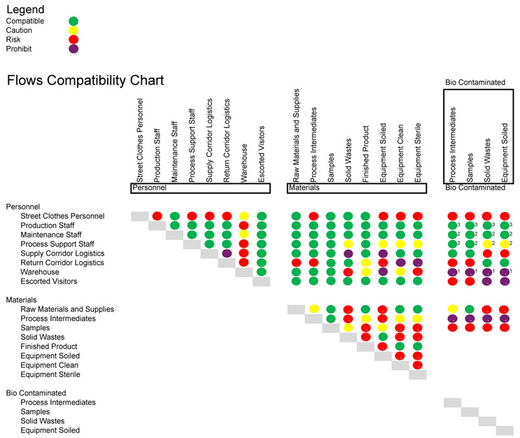
Of the various flows of materials and personnel accommodated in the facility design and represented on its flow plans, some types may readily and safely coexist, such as clean equipment, new supplies, and gowned, neutral manufacturing staff, and some pairings may be cause for concern, such as clean equipment and wastes or soiled equipment. As illustration, the table below offers an example, high-level guide to evaluating the potential risks of common flows. It is not proposed as authoritative in any particular case.
Click on image to enlarge.
Sliding Scale Of Design Balanced With Procedure
In some instances, procedures alone can be engaged to address otherwise unwelcome common flows. Clear and obvious labelling, unique containers, color coding of gowning, etc., can be utilized to make clear the status of materials and personnel as supplements to comprehensive training in maintaining segregations and avoiding mix-up.
In others, no set of procedures alone can address concerns absent elements of facility design. An example of such a condition is transition spaces at entry and exit from a classified manufacturing suite. Protection of the higher cleanliness air classified space with air pressure cascades cannot be accomplished by procedure alone. Transition spaces are a necessary part of successful design and operations in this case.
Most commonly, a combination of design and procedure working in concert is engaged to address GMP concerns. Conceptually, a continuum of approaches may be utilized from procedure alone at one end to layout alone at the opposite end.
At one extreme, facility design itself maintains segregation, contamination control, and avoidance of mix-up, without reliance on procedure. For example, the construction of separate manufacturing suites with access limitation features directly controls these flows, thereby preventing mix-up and direct contamination. Solid partitions and locked doors are difficult to transgress.
At the opposite end of the spectrum are conditions in which procedures alone can be engaged to resolve GMP cross flow concerns. Solid wastes may share a common flow path within a corridor if properly contained and labelled and/or if segregated in time from vulnerable counter flows. For example, supplies and raw materials may be transported through the common manufacturing corridor during daytime shifts, but only during night shifts are wastes removed from operating areas for transport out of the facility. Alternatively, wastes may be placed in containers that are clearly labelled or color-coded and wiped down upon egress from the manufacturing suite to a common circulation corridor concurrently shared with incoming raw materials and supplies.
Design is unable to fully address intersecting at-risk flows in all cases. For example, within a manufacturing suite, movements of staff, equipment, and materials can only be marginally constrained by design. Though processing equipment may be laid out in a progressive and linear configuration within the room or workstations defined to localize individual batch operations, staff, materials, supplies, clean equipment, soiled equipment, and wastes will nonetheless move across and along the length of the room throughout processing. Inevitably, the manufacturing space will have all states and conditions within it, both clean and soiled, new and used, raw materials, supplies, intermediates, samples, wastes, finished product, etc. Within such an environment, flow risks must, out of necessity, be controlled primarily by procedure.
Similarly, procedure alone cannot offer a self-sufficient solution to all cross-flow issues. In most instances, a cooperative combination of facility design and operating procedure is needed to accomplish GMP ends. Flow plans will indicate to the familiar reader where, and how much, reliance on procedure is planned.
Critical to the overall success of the design and procedure partnership is consistency throughout the facility. If careful segregation is undertaken in some areas of the operation but allowed to combine and cross in others, the benefits may be lost. For example, docks at the warehouse segregated into receiving, shipping, and waste are a direct expression of segregating flows. If, however, these distinct docks all connect to a common space, whether the warehouse itself or a common logistics corridor, the benefits of physical segregation are largely forfeit.
Evaluating Design Versus Procedure
When faced with strategic regulatory decisions on the continuum of design to procedure, how can a selection be evaluated?
Equipment Prep Suite Example
For discussion purposes, we’ll utilize a small-scale, familiar example of an equipment prep suite. In this functional area the GMP interest is to avoid carryover of production contamination from soiled equipment to clean and then sterile equipment and prevent mixing up equipment in different states. The range of examples shown below starts with a three-compartment suite, includes a two-compartment suite, and finishes with a single-room suite.
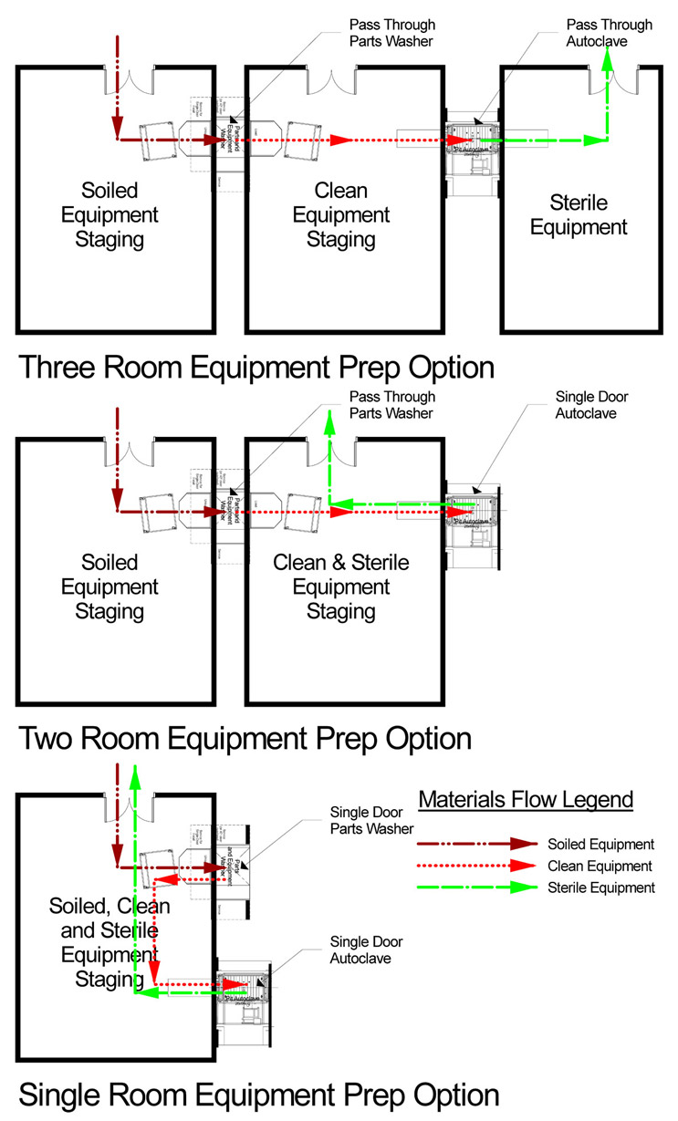
- The three-room process incorporates a first room dedicated only to soiled equipment that is loaded into pass-through washing equipment, removed in the middle room that is dedicated only to clean equipment that is then loaded into autoclaves, finally to be removed upon completion of the sterilization cycle in a third room dedicated solely to sterile equipment.
- The two-room suite retains a room dedicated to soiled equipment to be loaded into pass-through washers, just as in the first example. The second room, however, has a single-door autoclave in it and accommodates a combination of clean and sterile equipment simultaneously.
- The single-room example has a single-door washer and autoclave in it and all three states of equipment: soiled, clean, and sterile.
Of note here is that any of these examples may be acceptable for GMP use. What follows is a brief narrative comparison of the three options with a focus on how they accommodate GMP concerns for contamination and mix-up.
- The three-room suite relies largely on layout to assure segregation of soiled, clean, and sterile equipment as they each have dedicated rooms. Reliance on procedure and training is at a minimum. Size is the largest, as is capital cost, among the three alternatives. An inspector reviewing flow drawings or observing operations during a facility tour will have few, if any, questions related to this suite arrangement. Risk of failing GMP mandates is minimized.
- The two-room alternative segregates soiled equipment by dedicating a room, thereby assuring by layout avoidance of carryover of contamination to, or mix-up with, clean or sterile equipment. Clean and sterile equipment, however, co-occupy a single room. Space and capital costs are reduced as compared with the first option. Tracking accurately the status of any individual piece of equipment relies solely on procedure in this second room. Staff must properly label each piece and update labelling upon completion of sterilization. Transfer of equipment out to manufacturing use must carefully select status of equipment between uses and requirements for each process to be served. An inspector reviewing flow drawings or observing operations will likely ask how these objectives are met based both on written procedure and individual knowledge and practice of approved procedure in operation. Risk of mix-up between clean and sterile equipment will always be present and must be avoided by staff training and compliance monitoring.
- The single-room arrangement has no dedicated space assigned to any equipment cleanliness state. All three cleanliness states co-occupy the single room simultaneously. The labelling and tracking challenge described in the two-room option above is increased to three states; however, no amount of labelling can avoid the risk of carryover contamination from soiled equipment to either clean or sterile. In practice, lines on the floor are sometimes used to zone “parking” spots for equipment in differing states of cleanliness. This is the smallest and least expensive alternative among the three options. An inspector may ask many questions, review approved procedures, and question operations staff in the field in order to achieve assurance that this option is functioning acceptably. Risk of carryover contamination and mix-up between soiled, clean, and sterile equipment will always be present and must be avoided through staff training and compliance monitoring. It may not be possible to satisfactorily ameliorate these risks through procedure.
During the design process the owner/operator of the facility must evaluate these alternatives in light of the risk profile for the specific use. At one end of the spectrum is a solution that is reliable by design. Essentially, it is an intrinsically safe solution. And at the other end is a higher-risk layout that may be operated in a safe manner reliant upon procedure, training, and compliance. Even if so, the single-room option will be continuously subject to greater risk of failure in GMP terms of contamination and mix up. If the equipment prep area serves a single product manufactured in a single suite, these risks may be acceptable. If the equipment prep area serves a multi-product, multiple suite facility, the assurance of the three-compartment option may be more attractive.
Facility Overall Flows Discussion
The types of regulatory and operations design drivers described above for the focused case of an equipment prep suite can be discussed for the overall facility layout as well.
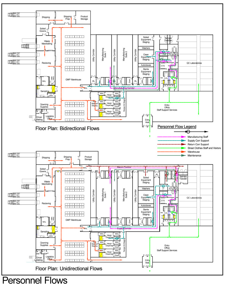
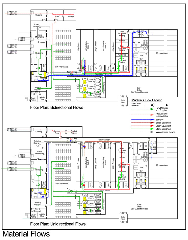
In terms of flows, each manufacturing suite needs to be supplied with staff, supplies, raw materials, etc., on the incoming side, and products, samples, wastes, and exiting staff must be removed. In general terms, these in and out flowing streams occur concurrently and continuously unless limited by procedure. Should all incoming and outgoing flows share a physical path at any point within the facility, the opportunity for undesirable results exists. If distinct physical paths can be defined, the opportunities do not exist. Example layouts of each configuration are shown below with flows for personnel and materials.
Click on images to enlarge.
The single manufacturing corridor layout is often referred to as a bidirectional flow arrangement as all flows into and out of manufacturing spaces come from, and return to, the same circulation system.
The layout incorporating two distinct corridor/circulation systems, each dedicated to either incoming or outgoing flows, is frequently called a unidirectional flow layout, as flows proceed in one direction through each manufacturing space.
Flows Beyond The GMP Core
Of note here is that the benefits or exposures to the risks of common flows described above are not limited to the GMP core, nor to air classified space. Any movement of people and materials within the facility can be subject to contamination and/or mix-up. For this reason, it is desirable for loading docks at the receiving area to be separate for receiving, shipping, and waste removals. Note in the single corridor layout example above that separate docks are shown, but all flows into and from within the facility lead to them via common corridors and through the warehouse. By comparison, the two-corridor example extends flow segregation beyond the GMP core to the exterior for all flow categories.
Neutral Supply
Among our interests in design and development of procedure is to deliver and assure neutral, non-contaminated people and materials to the manufacturing process. Given the only partial effectiveness of outgoing transition spaces in clearing objects and people of contaminants, returning these exiting flows to a single common path presents the risk of inadvertently transferring contaminants to incoming fresh supplies, equipment, and raw materials, contaminating incoming flows in the same space. Consequences of this exposure may be amplified in multi-product manufacturing facilities but are undesirable in any facility.
Among the primary advantages of the two-corridor system illustrated above is that this opportunity for contamination and mix-up is avoided altogether. Outgoing flows of wastes, samples, products, and soiled equipment follow a separate path that does not share any space with incoming clean, neutral flows.
People Are Unique
Of all the things we plan for and track with flows, people, particularly staff, are unique and are due specific thought. For incoming raw materials, the material itself is consumed by the process and packaging becomes waste and leaves the facility. Similarly for many supplies, they are new, fresh, clean, or sterile upon receipt, are used in the normal sequence of manufacturing events, and in due course become waste and leave the facility, never to return. Products are labelled, packaged, and shipped. Samples are taken to the laboratories, tested, and are not returned. Reusable and portable equipment can be washed and sterilized by automated and validated systems that reliably and repeatedly result in a clean or sterile and neutral state before they are returned to manufacturing. People, on the other hand, serially and continuously recycle through the facility, entering and exiting GMP manufacturing areas multiple times each shift and are not subject to clearance systems that are automated or able to be validated. Experience in the industry indicates that in many instances, it is the people who carry and introduce contaminants to manufacturing spaces and processes.
Designers and manufacturers must develop an answer to the question: At what point, and following what activity or series of activities and transitions, is a member of the staff sufficiently “cleared” of materials, products, and contaminants to be designated “neutral” once again? The answer may vary substantially, dependent on specifics of the facility, process components, and nature of manufacturing. In some, simply degowning upon exit from the manufacturing suite may be deemed sufficient to the risks. This would of necessity be the case in a bidirectional flow facility. Other facilities, for example, those that handle live organisms in manufacturing, may require that a member of staff who has worked within the live organism area leave the facility at the end of their shift and return another day before accessing a manufacturing area for processing post-clearance materials or another product. Yet other facilities direct exiting staff unidirectionally via a return corridor to the locker facility to replace plant uniforming before returning to the supply corridor for reentry to manufacturing suites.
Clearly, the answer to the unique questions of clearance of staff upon exit are critical to design of a facility and accompanying procedures.
Bidirectional Versus Unidirectional Flows
In the case of a manufacturing facility that produces a single product, or multiple products by campaign, and based upon closed, fixed, and automated process systems cleaned in place, there may be little risk associated with bidirectional flows. In such a facility there are often relatively few staff and little direct contact with the product during manufacturing. Degowning of staff upon egress from a manufacturing suite to the manufacturing corridor may be sufficient to satisfy the risk of contamination to the relatively few materials, supplies, and equipment transported therein.
Even in this case there nevertheless may exist incentives for segregation upstream to downstream. Some biologics-based products have an initial state previous to viral inactivation (pre-VI), followed by a post viral inactivation phase (post-VI) that are strictly segregated in space and equipment in order to avoid inadvertent recontamination with pre-VI materials once clearance or inactivation in the process is complete.
In the case of a facility that manufactures multiple products on a concurrent basis and utilizes a large array of materials, supplies, and portable equipment or single-use equipment, the risks of contamination and mix-up inherent in bidirectional flow may be assessed as too great. Such an assessment may drive a unidirectional flow layout for the facility design. An example of such a facility is a cell therapy facility manufacturing autologous therapy products on a commercial scale.
In terms of the performance of a layout in responding to GMP issues, a unidirectional flow design is the highest standard. Organizationally and hierarchically, it provides the highest level of segregation of flows feasible by layout, in order to assure environmental quality and to avoid contamination and mix-up.
The Design–Procedure Continuum
Design
Design features have the advantage that they are difficult to transgress. A partition or locked door is likely to succeed in limiting flow paths with no reliance on training or individual conformance. To borrow a term from electrical engineering, designed-in solutions offer “intrinsically safe” approaches to GMP concerns.
Procedure
At the outset, procedures must be created to specifically address the detailed conditions in place at an individual facility. Typically, a procedure incorporates a series of steps and activities or movements that are to occur in a particular order, at a particular time, or under a specific set of circumstances.
Once the procedure is approved, detailed training programs must be developed. Training and refreshing of trained individuals is then an ongoing and continuous program throughout the life and operation of the facility.
The training of staff must both be successful in conveying the required behaviors and be followed faithfully by all members of the staff. Both become subjects of monitoring and confirmation for the life of the facility.
All the above facets of procedure are subjects of examination by inspectors of many types. These include at minimum, governmental regulatory inspections, client company inspections in the case of contract manufacturing, in-house or corporate quality assurance reviews and inspections, etc. Communications and explanation/defense of procedures as sufficient to GMP issues is inherently an ongoing and routine element of a procedure based approach.
An additional feature of procedure-based approaches is that they may be more readily altered than approaches based on design. This flexibility may have beneficial or deleterious effects. Alterations can be undertaken by future generations of staff that undermine the functionality of GMP effectiveness learned and put in place by predecessors from objective experience. Often, procedures detail what to do, but not necessarily why or how the rules came about. Alternatively, procedural flexibility may allow incorporation of new products, regulations, or technologies with decreased disruption.
Summary
As a practical matter, once a reviewer or inspector sees a designed GMP solution in facility layouts and represented in flow plans, their concerns and questions will be settled without further discussion. Where the layouts and flow plans show crossing paths and common flows, a series of additional questions must be asked and research undertaken to achieve assurance.
About The Author:
Geoff Middleton is an architect with cGMA, Inc. He has more than 30 years of experience designing cGMP, regulated products, pharmaceutical, and biologics manufacturing facilities of a wide breadth of sizes and types, all over the world.

